


$220 SAVE $130 = 37.0% Western Digital 16.0TB Western Digital Ultrastar DC HC550 3.5-in… in Storage: Hard Drives
|
|

|
|

|
10 Kilowatt Lithium Battery System in Mercedes Sprinter: Challenges in Routing/Organizing/Placement

Photographer and cyclist and Mac expert and software engineer Lloyd Chambers is available for consulting on general Sprinter considerations at his usual consulting rates via phone, or in person in the Palo Alto, CA area. Save yourself hours and mistakes by discussing issues up-front. More about Lloyd....
Continued from 10 Kilowatt Lithium Battery System in Mercedes Sprinter: Parts and Wiring Overview.
This page discusses some of the challenges of dual batteries and dual inverters. The two competing challenges are:
- Placement of the batteries and inverters so as to maximize available space for other purposes.
- Minimizing cable lengths to minimize voltage losses all while keeping the take-off points electrically symmetric for consistent and reliable performance.
- Dealing with sixteen total welding cables of 4/0 and 1/0 sizes, a space/routing issue.
Wiring dual inverters to dual batteries and dual bus bars and fuses using 4/0 cables in a confined space is no simple matter, unless one is willing to sacrifice interior space, which I was not. Moreover, my usage constraints made it particularly challenging, e.g., a large table/desk free and clear above and below. Users with a kitchen in a larger-wheelbase sprinter might be able to, for example, place the batteries side by side under a counter in which no leg or kick room is needed and perhaps make things simpler.
Other interior configurations might be easier, such as in larger Sprinter vans with more available space and a different interior layout, or if a single inverter is sufficient. A single inverter/charge is likely enough for most users, but if one is spending over $12K on 800 amps of lithium batteries, it seems silly at best to hamstring power usage and charging rate with a single inverter/charger.
Shown below, 4/0 welding cable, very difficult to work with in cramped spaces. Use 1/0 for runs shorter than 18 inches as it is much easier to work with.
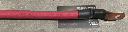
Not simple to route/manage while keeping all symmetric!
Planning the layout: multiple constraints
Cabling-up dual batteries and dual inverters requires careful planning because it is not just a layout issue (easy enough by using up space/volume), but also a space usage issue and especially important, an efficiency issue: voltage drops if the cabling is too long. A household electric space heater of 1500 watts, one of the comforts of van living (!), consumes about 1850 DC watts. Inappropriate cabling can sap voltage and overtax the system and/or throw dual batteries into imbalance.
Taking all these constraints into account, a 144-inch wheelbase Sprinter leaves little room to place two large batteries along with wiring and outlets to/from both inverters (if one wishes to maximize space for other uses).
My solution after choosing battery placement was to bolt the fuses, bus bars and inverters underneath my sturdy 44 X 29 inch hickory table/desk (hickory is the most robust and strongest American wood of all). There was no other place to install these items without losing critical space for my uses. The result is a packed under-table cabling “grand central junction”. Much pondering did not find a cleaner solution given all the constraints of both inverters and charging and the desire for keeping usable space free and minimizing voltage losses. In short, not as clean and neat as would be desirable, yet it is outrageously robust. Cable crowding is thus an acceptable tradeoff.
This installation proved challenging: while there is plenty of area on the 48 X 29 inch table, preserving legroom and storage space under the table near the front constrains placement. Also, bus bars require separation if fireworks are to be avoided, and all cables should be of minimal length to avoid voltage losses. It was a tricky business to pre-plan all cable routing, and in the end, 4/0 cables are very thick and very unwieldy and must be matched in length as well! Do not underestimate just how challenging this is, even if one can lay out the parts in advance. It is critical that cable lengths be matched, so if one battery can get away with 2 feet of cable, but the other requires 7 feet due to battery placement (e.g., the NEG cable to one of my batteries), then dual 7-foot cables are required—this is what I ran into.
The dual Xantrex Freedom XC 2000W inverter/chargers were bolted on under the hickory table. Warning: hickory is very hard, so care is required to not break the screws. Sorbothane @AMAZON is used in many places (table, inverters, under batteries, etc) between contact surfaces to allow a little give on very rough roads.
Electrical symmetry
The most important point of all: a high performance dual-battery system MUST use symmetric cabling. That is, equal-length positive and negative cables from each battery to the bus bars. In practice given my battery layout, one cable had to be coiled; allow for such considerations when planning cable routing—it can get tight.
From bus bars to the inverters, cables need not match—the key is symmetric cabling to/from the bus bars so that both batteries see the same load.
The prior installation rammed this point home, with differences in current draw between batteries, even though the wiring was heavy duty. If one battery drops to 10% SoC (state of charge) and shuts off while the other still has 30% SoC, the dual battery system is crippled in terms of its load capacity. That in fact is what happened in spite of heavy duty wiring with the initial wiring (prior to the use of bus bars).
Here is the cabling required for my system, proven in practice to have nearly flawless operation right down to 10% SoC (90% depletion):
- One 4/0 cable from positive terminal of each battery to 250 amp fuse box thence from each to positive/hot bus bar, identical lengths for symmetry. We ended up keeping this total cable length to only 5 feet. The voltage calculator shows that at 160 amps over one cable (320 amps total, peak transient load), the voltage drop should be 0.078V to the bus bar—impressive for a 320 amp load! The short ~1 foot 1/0 cable to the inverter would lose another 0.038V for a total voltage drop of 0.116V while the system carries 320 amps. For context, a 1500-watt household space heater draws about 140 amps at full power, which would mean only about 0.051V drop—extremely low. The Lithionics batteries maintain 12.6/12.7V under that load dropping down to about 12.2V at 90% discharge.
- One 4/0 cable from negative terminal of each battery to bus bar, identical lengths for symmetry. We ended up needing 5-foot cables; even though one battery needed only ~1 foot, the other negative terminal needed 5 feet to get to the bus bar. Cable runs need a little extra length, since 4/0 cannot just be bent into places, so looping and arcs in practice are unavoidable.
- Dual 1/0 cables from alternator to wiring panel and thence to bus bar (for charging).
- One very short 1/0 cable from positive bus bar to each inverter (4/0 not needed for ~12 inch run, besides, 4/0 lugs won’t fit into the inverter).
- One very short 1/0 cable from negative bus bar to each inverter.
- Dual 4/0 grounding cables of equal length from chassis to negative/grounding bus bar. We ended up needing 7 feet for matching cables, one grounding point being farther away (dual grounding points from the NEG bus bar are wise).
That’s a LOT of cabling totalling 16 cables to two bus bars (8 cables each)! It’s not as elegant as I would have liked, but the space constraints made it tough: the 4/0 welding cable cannot just be bent and forced into place. One has to plan out where excess cabling length will be looped or routed for example, since the cables between the hot and ground bus bars *must* be identical for symmetric performance. Thus one cable (NEG terminal of farthest battery, not shown) has to be coiled (not shown, complicating matters a bit more.
Eight-bay Thunderbolt 3 high-performance storage for photo and video.
Hard drives or SSDs.
Non-RAID or RAID-0/1/4/5/10.
Capacities up to 144 Terabytes!
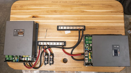
Pre-wiring, prior to flipping and installing the table
Shown below, the system has been pre-wired as to what can be done prior to installing the table (also the AC-IN cables, not yet attached). Remaining to be attached are the two 4/0 POS cables (one from each battery POS terminal) and the two 4/0 NEG cables (one to each battery NEG terminal). Plus of course the grounding wires from the NEG/ground bus bar to van chassis, and AC-OUT and smaller grounds from the chassis of each inverter (from the external post, such as seen at the bottom right of the inverter at left).
Sony A7R III + Zeiss Loxia 25mm f/2.4 Distagon
[low-res image for bot]
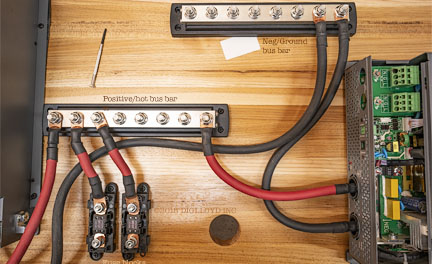
Closeup: bus bars and fuse blocks and inverter inputs
At right, the POS and NEG cables enter the inverter from the corresponding bus bar. Ditto for the left inverter. Not that symmetry is NOT necessary to/from the inverters from the bus bar. What matters is a symmetrical take-off to/from the bus bars from the batteries (2 equal-length POS and 2 equal-length NEG cables to/from batteries to bus bars, all 4/0).
Below, the very short cable runs from the fuse blocks to the POS bus bar are 1/0, being so short that 4/0 is not necessary plus it is difficult to force 4/0 at an angle as shown. The cables from the POS bus bar to each inverter are also very short and thus also 1/0. While 4/0 would be even better, 4/0 lugs would have had to be cut down to fit through the holes into the inverter.
The cables from the inverters to the NEG/ground bus bar are also 1/0, being fairly short also. While 4/0 for all would in theory be better, the lengths are short, and using 4/0 makes bends much more difficult, and would crowd the area even more (other cables have to route into this area from the back of the table (bottom near the hole), so crowding becomes an issue. It could be done of course by cutting down the four 4/0 lugs entering into the inverters and I’d have preferred it, but the reality is that the only load in which it would make a significant differences would be dual 1500 watt space heaters—and in that case waste heat is as good as heat from the inverters anyway. So I accepted this compromise.
One minor mistake: while using dual fuse blocks each with a 250 amp fuse (500 amps total), that’s actually problematic if a load exceeds 250 amps, because if one battery shuts off (upon reaching the depletion cut-off, I program in 13%), then the other fuse would quickly blow once a single battery and fuse block were forced to suddenly take up the entire load: 280 amps from dual batteries would likely surge to 300+ amps from a single battery, due to lower voltage. Then I’d have one blown fuse, quite a hassle to deal with in the confined space under the table. In the future I may install 300 or 400 amp fuses to forestall making such a mistake.
Sony A7R III + Zeiss Loxia 25mm f/2.4 Distagon
[low-res image for bot]
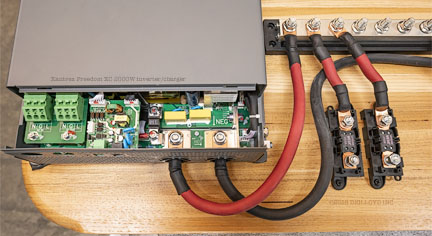
Below, the two fuse blocks accept up to 250 amps from each battery, routing that power to POS bus bar.
Sony A7R III + Zeiss Loxia 25mm f/2.4 Distagon
[low-res image for bot]
Seagate 22TB IronWolf Pro 7200 rpm SATA III 3.5" Internal NAS HDD (CMR)
SAVE $100
