


$220 SAVE $130 = 37.0% Western Digital 16.0TB Western Digital Ultrastar DC HC550 3.5-in… in Storage: Hard Drives
|
|

|
|

|
Phase 2: Inverter Mounting Locations

This page speaks to proposed inverter mounting in Phase 2.
Key notes:
- Existing battery will need to move forward about 4 inches to accomodate placing second battery just above the wheel well.
- Important: Leave 3-4 inch gap between batteries for tripod storage.
- Place APC or similar PDU units at appropriate locations, one for each inverter, bolted under table. These plug into one of the GFCI outlets on each inverter. The other GFCI outlet can be used directly for space heater or electric kettle or similar.
- Use sorbothane between table and inverter.
- No AC power outlets in van wall excepting the two (4?) shore power outlets.
- DC outlets to be installed facing down rather than out (?) to avoid plugs sticking out and limiting space usage. Maybe special little box under table with four (4) DC power plugs, robust ones.
- Move the batteries as close as feasible to the van wall to free up space for storage and flexible placement of inverters. Thus power cables to the inverter must run ABOVE the battery so there is no squashing-cable issue between wall and battery.
- Raise the battery higher if possible for more stowage under it (several pairs of boots/shoes.
- Remove all existing wall AC outlets because the batteries will abut the van wall.
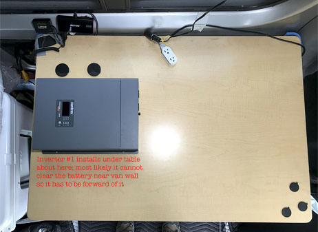
Mounting the 1st inverter/charger
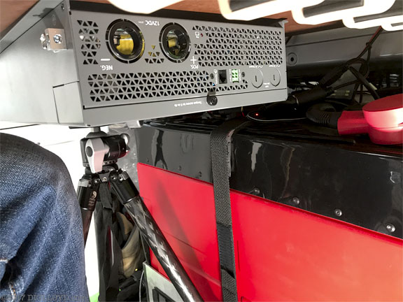
The first inverter charger should mount on the left side of the table with its GFCI outlets facing outward. Here we see the DC-in ports and the AC-in and AC-out ports. AC-in to be wired to conventional household plug which can be plugged/unplugged from conventional household 120V power outlet.
The butt-end of inverter #1 faces the butt-end of inverter #2, thus putting the GFCI outlets of each to the outer edges of the table, and keeping the bulky DC power cords between the two units and away from the outer edges of the table.
Tripod is shown here only becuase it is used to support theinverter so as to be able to take the picture.
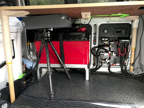
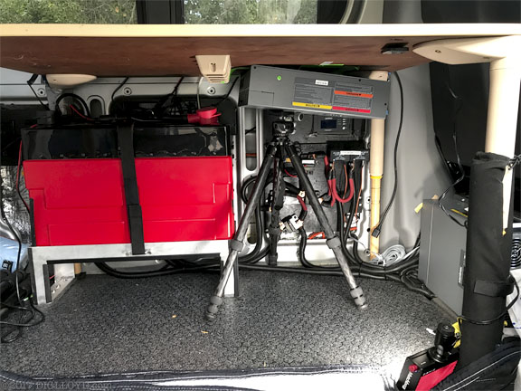
Mounting the 2nd inverter/charger
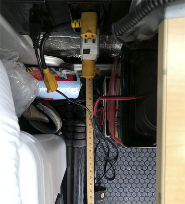
Move inverter seen at right off the floor and up under the new table. This frees up valuable floor space and offersshorter cable runs to the wiring panel.

These and other wall AC outlets must be removed because the 2nd battery will be blocking them.
Seagate 22TB IronWolf Pro 7200 rpm SATA III 3.5" Internal NAS HDD (CMR)
SAVE $100
